Figure Group
Figure Image

Figure image (.eps)
Figure image (.pdf)
Figure Caption
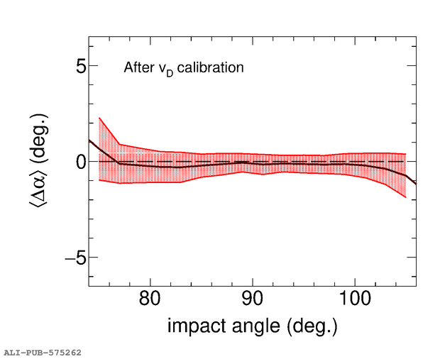
Left: $\Delta\alpha$ versus impact angle for a typical TRD chamber in Run~2, having a fixed uncalibrated drift velocity. The quoted values refer to the Run~2 calibration procedure (upper row) and to the new calibration scheme (lower row). Right: Average $\Delta\alpha$ versus impact angle for all TRD chambers after the calibration was applied. The red band shows the RMS of the distribution.
Detail description
Figure extracted from paper
