Figure Group
Figure Image

Figure image (.eps)
Figure image (.pdf)
Figure Caption
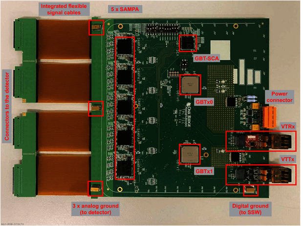
Layout of the final TPC FEC PCB Rev.\,1a The components are mounted on both sides of the board The figure shows the top side with five SAMPAs, two GBTx, one GBT-SCA, one VTRx, one VTTx and some other components On the bottom side a few additional small components and the connectors to the detector are placed. Figure taken from ~.
Detail description
Figure extracted from paper
