Figure Group
Figure Image

Figure image (.eps)
Figure image (.pdf)
Figure Caption
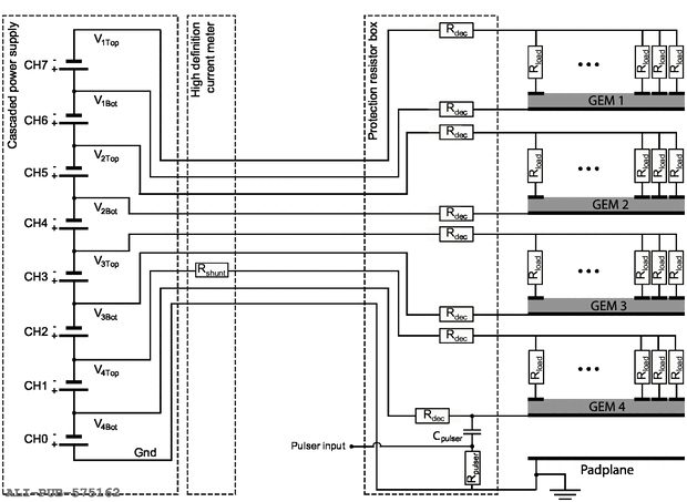
Detailed powering scheme of a GEM stack Each subsequent high-voltage channel is stacked on top of the lower-lying channel The ground reference is defined by a separate line connected to the ground of the detector The line for GEM\,4 top is shunted with a resistor ($R_{\text{shunt}}$) inside the high-definition current meter Each line is connected to the detector through a decoupling resistor ($R_{\text{dec}}$) The signal from a calibration pulser is coupled via a capacitor ($C_{\text{pulser}}$) to the line for GEM\,4 bottom Individual loading resistors ($R_{\text{load}}$) are mounted on all segments on the top sides of the GEMs Figure taken from~.
Detail description
Figure extracted from paper
