Figure Group
Figure Image

Figure image (.eps)
Figure Caption
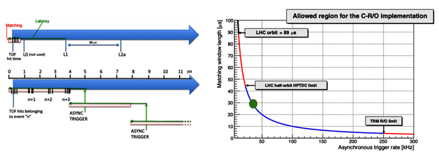
(left) HPTDC programming in Run 1 and 2 operations (top arrow) and in Run 3 (bottom arrow). The three trigger levels L0, L1 and L2a are replaced by a periodic trigger with a given frequency, mimicking a continuous readout. All hits (black lines) are read out and can be associated to physical events at a later stage. (right) Possible selection of parameters (fixed trigger frequency $f_\mathrm{T}$ and matching window width $m_\mathrm{w}$) to realize a continuous readout. The green circle corresponds to the chosen point of operations.
Detail description
Figure extracted from paper
